Grism-based Spectrograph Modeling
- Version
0.9 of 21-09-03, 13:16
- Author
Yannick Copin <y.copin@ipnl.in2p3.fr>
- Abstract
This module initially implemented the spectrograph optical model used for the TIGER-like integral field spectrograph (e.g. SAURON [Bacon01] and SNIFS [Lantz04]) data-reduction pipeline, and first presented in [Copin00]. It provides a flexible chromatic mapping between the input focal plane and the output detector plane, based on an effective simplified ray-tracing model of the key optical elements defining the spectrograph (collimator, prism, grating, camera), described by a restricted number of physically-motivated distortion parameters.


Optical modeling
The model only handles the geometrical part of the light propagation through the spectrograph, i.e. provides a mapping between a wavelength and a position in the entrance focal plane to a position in the detector plane (at the output focal plane). It is therefore assumed all the PSF and scattered light effects (related to focus, axial chromatic aberrations, diffusion, etc.) are modeled independently.
Optical elements (spectrogrism.spectrogrism)
The Spectrograph model includes optical elements between the input
focal plane and the output detector plane:
an optional
Telescope, which converts a direction in the sky into a position in the focal plane;a
Collimator, which converts a position (in the focal plane) into a direction;a
Grism(an association of aPrismand aGrating), which converts a direction into another direction depending on wavelength and dispersion order;a
Camera, which converts a direction into a position (in the detector plane);a
Detector, which actually project positions onto the translated and rotated detector.
Both Collimator and Camera include geometric quadratic radial
distortion and lateral colors (transverse chromatic aberrations).
Prism includes 3D-tilts.
Positions and directions
A 2D-position \((x, y)\) is encoded in complex number \(x + jy = r\,\exp(j\varphi)\).
A 2D-direction \((\theta, \phi)\) – where \(\theta\) is the angle between the optical axis \(Oz\) and the propagation direction, and \(\phi\) the phase in the transverse plane \((Oxy)\) – is encoded in complex number \(\tan(\theta)\,\exp(j\phi)\).
A 3D-direction is encoded by the coordinates of the unit-vector \((x, y, z)\).
Distortions (spectrogrism.distortion)
A
StructuredGridis a structured grid of (complex) 2D-positions, with plotting and distortion-adjustment facilities.GeometricDistortionimplements the full Brown-Conrady (achromatic) distortion model, including radial and tangential components of arbitrary orders.ChromaticDistortionis a minimal lateral-color distortion implementation.
SuperNova Integral Field Spectrograph (spectrogrism.snifs)
Figure: Modeling of 5×5 sources in the detector plane at 10 individual wavelengths, using the SNIFS-R optical configuration. Orders -1 (very top), 0 (undispersed), 1 (middle) and 2 (bottom) are represented. The size of the symbol somehow encodes the blaze function of the spectrograph.
Near Infrared Spectrometer and Photometer (spectrogrism.nisp)
Zemax simulations
The spectrogrism.spectrogrism optical model is used to simulate the
Near Infrared Spectrometer and Photometer (NISP) of EUCLID, mimicking full
sky-to-detector Zemax spectroscopic and photometric simulations for a nominal
NISP configuration (courtesy J. Zoubian).
Figure: Zemax sky-to-detector multi-order simulation of 17×17 sources in the detector plane at 13 individual wavelengths (outlined symbols) and minimally 1st-order-adjusted optical model using nominal NISP parameters (filled symbols), along with associated 0th- and 2nd-order predictions.
Questions regarding the current Zemax simulation:
input y-coordinates are offset by +0.85 deg
output y-coordinates are not centered: (dx, dy) = (+0.7, 179.8) mm, corresponding to (+0.7, -4.2) mm for centered y-coordinates
input position (+0.4, +1.25) is missing the 1.85 µm wavelength
NISP optical design
The NISP optical design is presented in [Grupp12] and updated in [Grupp14] (see Fig. 1).
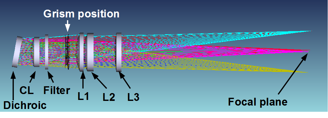
Fig. 1 The EUCLID f#20 to f#10 relay system including filter and grating position (from [Grupp12]).
It consists of:
an f/20 1.2 m diameter Korsch type three mirror telescope in off-axis configuration
the Corrector Lens assembly CoLA (fused silica)
depending on the observing mode:
- photometric mode (NISP-P):
a filter with mildly powered spherical entrance surface and flat exit surface (fused silica)
- spectroscopic mode (NISP-S):
a grism with mildly powered spherical entrance surface and binary optic (curved line) grating exit surface (fused silica)
These intrinsically static elements are placed in filter/grism wheels with limited position repeatibility.
the Camera Lens assembly CaLA (CaF2/S-FTM16/S-FTM16), providing an f/10 beam.
16 2k×2k IR detectors
The objective of this work is to assess the possibility to model in an effective way the NISP-S optical scheme in order to be able to predict multi-order spectrum locations from photometric catalogs.
References
SNIFS optical parametrization(SNfactory Technical Documentation)Redefinition of the blue grating(SNfactory Technical Documentation)NISP Technical Description (EUCL-LAM-OTH-7-001)